
|
|
|
|
by K5OE Some time ago, we ran
across these cool plans for a mobile vertical for 2 meters on the K5OE web
site which is no longer on the web, and we realized that it had a
very low angle of radiation designed for use
with the LEO satellites. Since it already has a very low angle of
radiation, why not adapt it for "base station use" for regular 2 meter
land based communications. It seemed to us that since the pattern was much
lower than many conventional base station home brewed antennas, why
not modify it for base station use to get our signal lower to the
ground where it is needed most instead of heating up lots of air at a
higher angles!
What follows is the complete article by K5OE that he has kindly shared with us on his mobile design with some suggested "mods" for using it on a fixed mount instead of your mobile for regular 2 meter simplex and repeater use....read on.....  Do you have trouble getting your mobile signal into the LEO satellites? Try this small 2 meter vertical antenna with your mobile rig or HT and enjoy more success in your uplink. I built this small vertical because I could not uplink very well at low elevations and I just could not bring myself to drill holes in the roof of my new truck to install a more substantial antenna. I had been using a very common 1/4 wl mag-mount with only marginal results. Design:
The antenna is an atypical vertical: instead of the common 1/4 wl vertical monopole or 1/4 wl ground plane with 1/4 wl radials, this design employs a 3/8 wl vertical section and short radials to complete the "ground plane." Effectively, an off-center-fed vertical dipole that does not rely on the earth or, in my case the truck body, to complete the bottom half of the antenna. This is an important point. The fact the antenna has a fully contained lower half, i.e., the ground plane, makes it very efficient. This is especially significant when compared to my mag-mount monopole antenna where the "ground plane" had to be completed through the coax, through the rig, then to the vehicle body. I suspect the mag-mount was not very efficient at all. The dipole is off-center-fed to get a better match to the feedline and the bottom "half" of the antenna is completed with capacitive reactance from the four shortened radials. This design has an honest 3 dBi of gain at 6' elevation (2 dBi free-space) with a suitable pattern for LEO communications--favoring the horizon. At 20' high, the same antenna exhibits almost 6 dBi of gain. The feedpoint is a nominal 50 Ohms at 146.850 mHz. Construction: The tee is arranged vertically with the top cap drilled for connection of all 5 elements (I used 6-32 stainless steel bolts/nuts/washers) and the bottom plug is drilled for connection of a magnet (optional). The coax is fed thru the
open side of the tee and connected directly to the elements via ring lugs.
Alternately, a lower-profile version could be constructed substituting a
coupling for the tee and drilling a hole in it for the coax to exit. I
connected the center of the coax to the mast (the vertical
section), and the shield to one of the radials using crimp style ring
terminals. I then wrapped some small gauge wire around the outside of the
cap, connecting all four radials together, and covered the assembly with
electrical tape and paint.
(The figure above shows the layout and dimensions (in cm)
of the elements.) The radials are angled down
at about 30 degrees. This angle can be adjusted to get the SWR perfect
once the vertical mast is trimmed for best SWR at the desired frequency,
but I found the effect minimal. You could also "wind" a coil of a few
turns in the center of the mast to lower the profile of the antenna
without affecting feedpoint impedance drastically or performance too much.
See picture on right, below. I did that to make it short enough to fit
under my garage door header and note no significant difference in SWR or
performance. 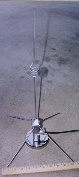 Testing an early "straight" prototype on the left and The final "shortened" model on the right above. (Pictures have been compressed in size slightly to fit page) Performance: Mission accomplished. I can now get "into" the birds at low elevations. On it's maiden journey out of the garage, I worked four stations (one was marine mobile) on an 8 degree AO-27 pass. If I could hear the bird, I could work it (as long as a "big gun" station did not have the bird already captured). At high elevations I found I could run on low power (about 3 Watts) and capture the bird with little difficulty. This antenna makes a nice
1/3 scaled companion to the 70 cm
Handi-Tenna for satellite work or can be used for any
fixed, mobile, or portable service. Since the elements are flexible 10
gauge wire, they can be readily folded and unfolded for backpacking.
K5OE Suggested modification for base station fixed location: See the project link below for a standard ground plane type antenna and look at the pictures to get some ideas of suggested methods for mounting. http://www.hamuniverse.com/kc0ynr2metergppvc.html You could also use a small metal bracket with a hole cut out that will accept an SO-239 bolted to it and then attach the radials to the bolts and the vertical section of the antenna to the center conductor of the SO-239, (mounted upside down of course),..mount it to a mast up high and enjoy...use your imagination and have fun with it! 73, N4UJW. Many thanks to Jerry, K5OE for sharing his expertise and fun with others!  Monitor police, fire, ham radio, rescue, ships and more!  Hamuniverse.com uses Green Geeks Web Hosting! |

